We bend steel, stainless steel, aluminium and galvanised sheet on a 7-axis AMADA press brake. Send a DXF or STEP file to receive a quotation and feasibility confirmation.

At ANBI-TECH, we have been CNC bending sheet metal in our Olkusz facility since 2008. Our AMADA HFE-M2-5012 EVO press brake handles parts up to 1000 mm long and sheet up to 8 mm thick. We specialise in small and medium precision components, not large-scale parts.
We work for industries requiring dimensional repeatability: automotive, electronics, machinery manufacturing, energy and food processing. We make prototypes primarily for projects leading to series production. We carry out quality control in accordance with ISO 9001:2015 and prepare a measurement report after the documentation scope has been agreed.
We prepare quotations from a DXF drawing or STEP model. For parts combining bending with CNC turning and CNC milling, we complete the whole production route in one facility – without coordination between subcontractors.
Our Olkusz facility operates an AMADA HFE-M2-5012 EVO press brake – a 7-axis CNC machine with the ECO-Inventer function:
Bend allowance and springback compensation are set in the program for the particular material, thickness, radius and geometry. The control system executes the programmed positions, while the operator checks the result and makes the necessary corrections.
We bend 5 material groups using selected machining parameters:
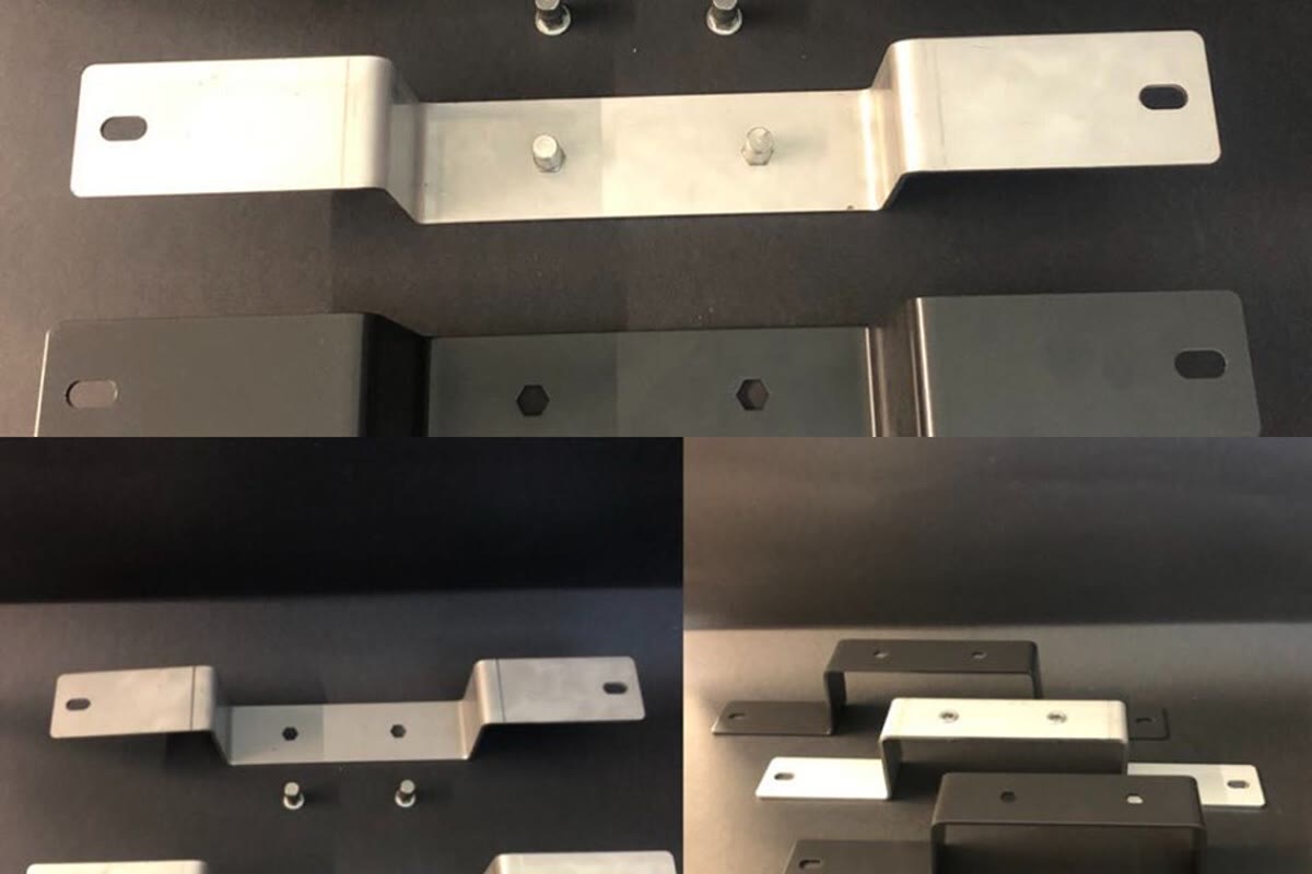
Automotive – component mounting brackets, enclosures for onboard-electronics elements, structural sheet metal for prototype vehicle bodies and sensor mountings. We agree tolerances from the drawing, with PPAP available on request.
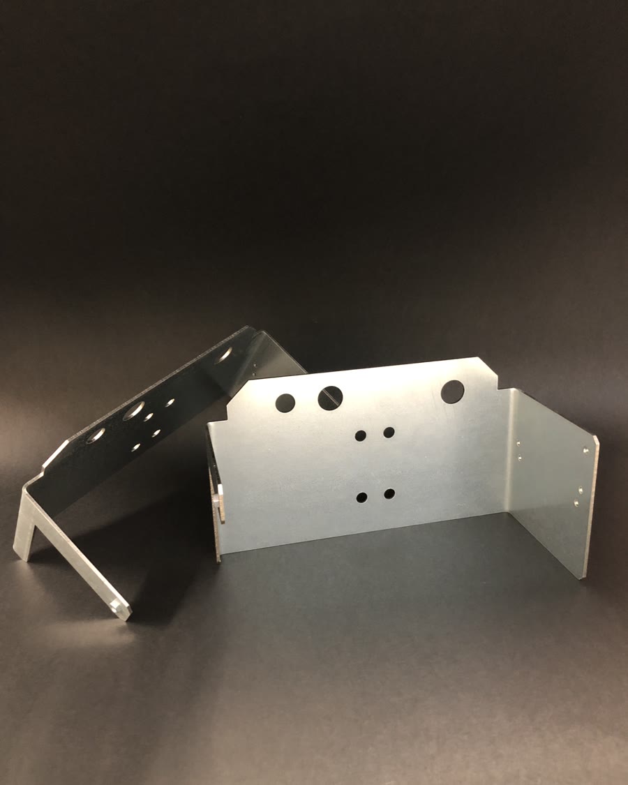
Electronics and automation – control-cabinet enclosures, measurement-device chassis, front panels, PCB mounting sheets and cable guards. Materials: galvanised steel, stainless steel and aluminium.
Machinery manufacturing – guards for moving parts (in accordance with EN ISO 14120), motor enclosures, service covers, media-routing channels and structural frame sheets. Material: S235JR / S355J2 up to 8 mm.
Industrial equipment – enclosures for packaging machinery, production-line panels, safety guards and housings for test and measurement equipment. We combine this work with CNC turning of mounting bushes and CNC milling of precision holes.
The applications described above are complemented by two industry groups:
Some parts are made in a combined cycle: profile cutting, milling mounting holes and bending to final dimensions. We complete the full cycle in one Olkusz facility.
View our completed projectsThe AMADA HFE-M2-5012 EVO press brake has operated in our facility since 2019. It is a seven-axis machine with 50 tonnes of press force, bend length up to 1000 mm and sheet thickness up to 8 mm, equipped with the energy-efficient ECO-Inventer system. We provide a measurement report on request.
View our machinery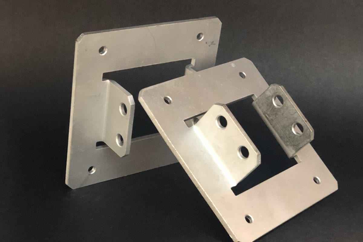
Tooling – we select the punch and die for the sheet grade, thickness and required bend radius. Die width determines the bending force, internal radius and developed part length.
Process optimisation – we plan the bend sequence when preparing the program, together with tool selection. For series production, we retain programs in the library – subsequent batches start with calibration rather than programming from scratch.
Quality control – the FAI, dimensional-inspection and measurement-report scope is agreed for each order. We carry out production under the ISO 9001:2015 quality management system.
Send a DXF drawing or STEP model – we will calculate the material, press-brake time and unit cost. We will check whether the design can be made on our press brake and advise how to optimise it for bending.
We make prototypes primarily for projects leading to series production. We operate under the ISO 9001:2015 system, and agree the scope of the dimensional-inspection report and completeness documentation for each order. Address: Olewin 50A, 32-300 Olkusz (Lesser Poland).
See also CNC cutting and CNC milling.
CNC bending is the forming of sheet metal on a press brake, in which the punch (upper tool) presses the sheet into the die (lower tool) at a precisely controlled angle. Numerical control manages the position of the punch, backgauge and the sequence of bends – the operator prepares the program and the machine maintains the angle of successive parts within the agreed tolerance.
Unlike cutting or milling, the process does not remove material – it reforms it. The sheet remains in one piece, while the bend line produces an edge with a controlled internal radius and precise angle.
The press brake in the ANBI-TECH machine park has seven controlled axes that support the positioning of the beam and backgauges. The arrangement helps to set the bend line, height and backgauge position accurately for simple, asymmetric and multi-bend parts.
The control system automatically sets the programmed axis positions, while the operator handles, turns and repositions the part between successive bends and checks the process result.
After pressure is released, every material partly returns to its previous geometry. This phenomenon is called springback (springback). Its value depends on the material, sheet thickness and bend radius.
The second parameter – bend allowance (bend allowance) – is the developed length of sheet required for the bent part to have the designed external dimensions. It results from the neutral axis of the sheet not lying exactly halfway through its thickness.
The process engineer sets the bend allowance and springback compensation in the program according to the material grade and thickness, radius and trial-bend result. The control system executes the programmed positions, while the operator verifies the result and makes the necessary corrections.
The bend radius depends on the ductility of the material. The less ductile the material is (harder steel or a high-strength alloy), the greater the minimum radius needed to prevent cracking on the tensile side. Typical values for the most frequently bent materials (r = internal radius, t = sheet thickness):
The maximum declared sheet thickness is 8 mm. Actual feasibility depends on the material, geometry, bend length and required operation.
| Material | Typical grades | Min. bend radius |
|---|---|---|
| Structural carbon steel | S235JR, S355J2, DC01, DC03 | r ≥ 0.5 × t |
| Austenitic stainless steel | 1.4301 (304), 1.4404 (316L) | r ≥ 1.0 × t |
| Aluminium | Grades EN AW-1050, EN AW-5754 and EN AW-6082 | r ≥ 2.0 × t |
| Galvanised sheet | DX51D+Z, DX52D+Z | r ≥ 1.0 × t |
| Copper / brass | Grades Cu-ETP and CuZn37 | r ≥ 0.5 × t |
For parts requiring a smaller radius (for example r < 0.5×t in stainless steel), sharp-radius bending is possible, but the risk of cracking on the tensile side increases. In that case, we require prior process consultation and a trial part.
There is no single bending tolerance that applies to every part. The accuracy of the angle and flange length depends on the grade and thickness of the sheet, die width, bent-edge length and how far the bend is from the edge. We therefore agree the tolerance for a specific drawing rather than applying one value to every order.
How to prepare an enquiry: the greatest time saving comes from stating on the drawing which dimensions are critical and what angular deviation is acceptable. For parts with a tight angle or a bend close to the edge, we make a trial bend and adjust the program before starting the batch.
The two technologies are often confused, but they produce different results:
In practice: a part with 4-6 bends at different angles and tight dimensional tolerance – press brake. A flat 600×400 mm enclosure with four perimeter flanges – folding machine.
Most parts that we bend undergo other processes at our facility first:
Completing the whole route at one facility shortens the production cycle and eliminates coordination between several subcontractors. Every stage follows the same inspection documentation and is covered by the ISO 9001:2015 system.
Bending prices are set using one of three models:
The unit cost in production runs is affected by the type and thickness of sheet metal, number of bends, set-up time (punch and die selection), quantity and dimensional-inspection requirements. We quote every order individually from a DXF/STEP drawing.
We calculate the flat length using bend allowance. The simplest formula for a 90° angle is:
Formula: L = A + B + BA, where A and B are the lengths of both flanges (measured to the inside edge) and BA is the bend allowance.
Bend allowance depends on sheet thickness (t), internal radius (R) and K-factor (usually 0.33-0.5):
BA = (π/180) × angle × (R + K × t)
In practice, we set the bend allowance in the program for the particular material, thickness, radius and geometry. If a customer sends a flat pattern from their own CAD program, we verify it before machining begins and report any discrepancies.
These are two different methods of calculating sheet-metal flat length. The choice depends on whether the designer dimensions parts from the outside or inside.
Both lead to the same flat length, but require the CAD dimensioning convention to be agreed in advance. When receiving a DXF file, we always ask which standard the customer used.
Yes, we bend galvanised sheet, but the result depends on the sheet grade and thickness, type and condition of the coating, bend radius, rolling direction and selected tooling.
We assess the risk of coating cracks or marks for the specific part. If necessary, we carry out a trial and agree additional edge protection after bending.
Our tooling inventory includes:
We determine the punch and die for a particular part when preparing the program, together with the bend sequence.
Yes, but they require geometric verification. The risk of hole deformation depends on its diameter, distance from the bend line, radius, sheet grade and thickness, and rolling direction.
Before laser cutting or milling holes, we verify the distances in the flat pattern from the DXF or STEP file. If the geometry is borderline, we suggest moving the hole or making it after bending, depending on the required positional accuracy.
Lead times depend on three factors: quantity, availability of material in stock and the production queue on the day the order is accepted.
For urgent orders, we agree production priority – we always state a specific date together with the quotation, rather than giving an estimate.
For the automotive industry, we offer an extended documentation scope agreed at the enquiry stage:
We operate under the ISO 9001:2015 system. We do not hold IATF 16949 certification and do not serve tier-1 OEM supply requiring that certification. Quality and documentation requirements for an automotive project are agreed individually.
The minimum bend radius (r) depends on material ductility and thickness (t). The less ductile the material, the larger the minimum radius.
For parts with a smaller-than-standard radius, we make a trial bend – documenting any cracking before the full production run.
On a press brake, the punch presses the sheet into the die to create the bend. In air bending, a gap remains between the punch and die, and the angle results from punch penetration depth, so different angles can be produced with one tool. In bottoming, the sheet fills the die without a gap, and the punch and die must precisely match each other, so each angle requires a separate tool set.
We publish references we have received and reviews from the ANBI-TECH business profile on Google Maps. The English versions are faithful translations of the Polish originals.
I can wholeheartedly recommend Anbi-Tech as a reliable and professional partner in machining and in manufacturing parts for the pharmaceutical industry. This is the third company where I have had the pleasure of working with Anbi-Tech, and the cooperation has been of the highest standard every time.
The pharmaceutical industry is exceptionally demanding: precision, on-time delivery, material quality and a full understanding of the customer’s needs all matter. Anbi-Tech has repeatedly proved that it is very well suited to this environment. The company has manufactured change parts, spare parts, filling needles, conveyor screws, components for dispensing powders and liquids, and many other production components for us.
The quality of the parts deserves particular recognition, whether they are made from 316L and 304 stainless steel or plastics such as POM, polyurethane and polycarbonate. The components are manufactured to a very high standard, with close attention to accuracy and detail, which is crucial in our industry.
Anbi-Tech has literally ‘saved our skin’ on many occasions in emergencies where time, a rapid response and a flexible approach to the customer mattered. A major strength of the company is its modern machinery, which enables it to complete even highly demanding projects while maintaining the highest standard of workmanship.
The people are equally important: the company’s staff always show complete commitment and a willingness to cooperate and provide technical support. Their extensive experience, professionalism and collaborative approach to customers are clear to see.
In pharmaceuticals, the ‘paperwork’, meaning certificates, is also important. The certificates have never been questioned during customer or regulatory audits, for example by GIF.
I strongly recommend working with Anbi-Tech to any company looking for a proven, reliable and quality-focused technical partner.
Dariusz Stachowicz, Senior Maintenance Manager, Polfa Warszawa S.A.
We had a very good experience working with Anbi-Tech on a new production line project for a bottling plant. Using a bottle sample and components from the old line, its engineer prepared the design and documentation for new change parts in SolidWorks. Anbi-Tech then manufactured timing screws, star wheels, drive components, bottle orienters, bottle turners and feeding components, among other items.
A major advantage is the end-to-end approach, from analysis and design through to the manufacture of finished components. Their considerable technical experience, precision and ability to solve unusual problems are clear. I recommend them.
Bartłomiej Ć, Specialist, ORLEN
We work with Anbi-Tech to manufacture parts and technical components for our projects. We value them above all for their workmanship, on-time delivery and excellent communication. When requirements are unusual, they can advise us and find a solution instead of simply manufacturing a part from a drawing. A reliable partner that I am happy to recommend.
Marek P., Production Manager, Triccor
A reliable company with extensive experience! They manufacture parts from steel, aluminium and specialist plastics such as POM and PTFE. Every service, whether turning, milling or CNC cutting, is carried out perfectly and with attention to the smallest detail. Excellent communication, professional advice and consistently on-time delivery. I wholeheartedly recommend them to anyone who needs reliable components.
Damian Lab
For a quotation, send a PDF or DXF drawing or a STEP model with dimensions. State the material, the number of pieces and the quality requirements. A photograph of the part alone, without dimensions, does not allow a reliable quotation to be prepared.
If the project combines several operations, we will agree the scope of machining, inspection, assembly and processes carried out by partners.

Tel.: +48 32 788 70 10
Mobile: +48 693 726 777
Mobile: +48 693 726 127

Olewin 50A, 32-300 Olkusz
VAT ID: PL6372190715

anbi@anbi-tech.pl